
Earthing Design on Difficult Ground: Why Your Electrical Engineers Deserve a Better Ground Model

Every substation, switchyard and live electrical structure depends on an earthing system, which is the buried network of conductors that carries fault current and lightning safely into the ground and keeps touch and step voltages within tolerable limits during a fault.
Earthing systems are designed by electrical specialists to well-established standards, and this article is not about doing their job. It is about improving one of the critical inputs their job depends on. Every earthing calculation rests on a model of the ground: its electrical resistivity, soil/rock layering, groundwater, chemistry and likely behaviour over the asset’s life.
Give the designer a thin ground model and they will, quite properly, allow for uncertainty. Give them a well-characterised one and the design can be safer where it matters and more economical where it does not. On benign, uniform sites, the difference may be modest. On variable, wet, coastal, seismically-active, cavernous or geothermal ground, it can separate an earthing system that is fit for the site from one that is either silently overbuilt or quietly inadequate.
The cost of a thin ground model runs both ways
Ground resistivity describes how readily soil and rock conduct electricity. It is one of the most influential and variable inputs to earthing design, changing by orders of magnitude between across wet clays and dry gravels and rock, also varying with depth, location, moisture content and season.
Design against an optimistic model and the installed system may underperform, creating a safety problem discovered at commissioning and corrected by reopening a finished site. Design against a pessimistic or poorly defined model and the project may pay for copper, electrodes, trenching and land area it never needed. That cost can remain invisible because overbuilt earthing still works.
Both outcomes have the same root source which is uncertainty in the ground model. The electrical design may be sound, but it can only be as proportionate as the information beneath it.
What the ground team brings
Resistivity first

The foundation is measured resistivity. Targeted traverses and soundings provide the apparent resistivity data needed to develop the uniform or layered soil models used by earthing designers. Where the site is large, laterally variable or geologically complex, Electrical Resistivity Tomography can add continuous two-dimensional or three-dimensional information on how resistivity changes across the site and with depth.
That mapping can do more than improve the model. It may identify areas where conductive ground is accessible at practical depth, where deep electrodes are likely to be effective, or where adverse ground should be avoided. On large sites and corridors, this can inform layout and siting before the earthing system is forced to compensate for a fixed location. An early siting conversation can create savings that no amount of late optimisation can recover.
Beyond resistivity: what else the ground model tells the designer
Resistivity tells the designer how the ground behaved when it was measured. The wider ground model helps explain why, how representative the result is, and how conditions may change over decades. That is the difference between supplying a number and supplying an understanding.
Groundwater: depth, fluctuation and flow
Moisture strongly influences soil resistivity. A site surveyed in a wet July could appear far more conductive than the same site in a dry March, while the earthing system must perform during the least favourable credible conditions.
Understanding groundwater depth and seasonal fluctuation helps the designer judge how representative the measurements are and select defensible design values rather than applying a blanket allowance. It also identifies long-term risks. Drainage, abstraction or sustained drying can reduce soil moisture and degrade earthing performance over the asset’s life.

Soil chemistry and aggressivity
An earthing system is bare buried metal expected to remain effective for decades. Coastal chlorides, low pH, sulphates, contaminated soils and industrial fill can accelerate corrosion of conductors and, critically, their connections.
Characterising the ground allows materials and corrosion protection to be specified where they are needed rather than everywhere. It may also allow hostile zones to be avoided. Contamination information brings a second benefit: finding affected ground during investigation is far cheaper than discovering it while excavating and disposing of material from earthing trenches.
Seismic behaviour and liquefaction
Liquefaction and lateral spreading can deform a buried grid, damage conductors, break joints or reduce electrode contact at the moment reliable earthing matters most.
A design informed by the extent and severity of ground deformation can route and detail the system to better tolerate movement, or coordinate it with ground improvement already planned for foundations. For resilient infrastructure, post-earthquake earthing performance begins with the geotechnical model.

The genuinely difficult ground: karst and geothermal sites
In limestone terrain, cavities and highly variable weathering can create complex resistivity patterns and uncertain current paths while also presenting a physical ground-stability risk. ERT can support the earthing model while helping identify anomalies that may indicate voids or weakened ground: one investigation answering two project questions.
Geothermal sites combine elevated temperatures, aggressive chemistry, weak or evolving ground and strongly three-dimensional resistivity conditions. These are precisely the sites where assumed values and standard details are least reliable, and where measured, geology-aware and chemistry-aware inputs provide the greatest value.
One coordinated campaign from the beginning
This does not always require a separate investigation. Most energy projects already need geotechnical work for foundations, earthworks and natural hazards. The additional cost of capturing earthing inputs within that campaign is often modest: resistivity measurements coordinated with boreholes, groundwater observed rather than guessed, chemistry sampled while the holes are open, and seismic assessment shared across foundation and earthing decisions.
Run as a late addition, the same work requires another mobilisation, arrives after the layout is fixed and leaves the designer conservative about anything it did not cover. The economical version is the early, integrated and measured version.
Where we come in, and where we do not
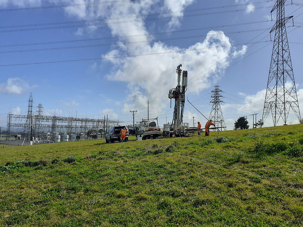
Earthing design belongs to the electrical engineers, and we do not do that. Cook Costello provides the ground portion of the partnership: geophysicists who measure resistivity using targeted traverses, soundings and ERT across sites and corridors, and geotechnical engineers who place the geology, groundwater, chemistry and seismic behaviour behind the numbers.
We deliver that information as a ground model suited to the earthing designer’s workflow and integrate it with the investigation the project already needs. On challenging sites, the result is an electrical design based on measured conditions rather than broad assumptions, with better-defined safety risks and fewer silent margins standing in for missing knowledge.
For substations, switchyards, renewable-energy connections and transmission projects on difficult ground, bring the ground and electrical teams together early. One coordinated investigation can answer both sets of questions.
OR


